What is a Wire Resistance Calculator?
A wire resistance calculator is an electrical engineering tool that computes the electrical resistance of a wire based on its material, dimensions, and operating temperature. This essential tool helps engineers and electricians design electrical systems, select appropriate wire sizes, and predict voltage drops.
Wire resistance is crucial for electrical installations as it directly affects power loss, voltage drop, and heat generation. Temperature plays a significant role since resistance increases with temperature for most conductive materials.
How the Wire Resistance Calculator Works
The calculator uses the fundamental resistance formula with temperature compensation to provide accurate results across different operating conditions.
Resistance Formula with Temperature Compensation
R =
ρ ×
LA
× [1 +
α(
T - 20)]
Where:
- R = Resistance (Ω)
- ρ = Resistivity at 20°C (Ω·m)
- L = Wire length (m)
- A = Cross-sectional area (m²)
- α = Temperature coefficient (/°C)
- T = Operating temperature (°C)
Cross-Sectional Area
Key Features
- Multiple conductor materials (copper, aluminum, silver, gold, tungsten, nickel)
- Temperature compensation for accurate resistance calculation
- Support for different wire size standards (AWG, mm, inch)
- Length units in meters and feet
- Temperature units in Celsius and Fahrenheit
- Real-time calculation with instant results
- Voltage drop, % drop and I²R power loss with NEC 3%/5% pass-fail check
- Mobile-friendly responsive design
- Automatic material property selection
- Free to use with no registration
Professional Applications
- Electrical system design and planning
- Wire sizing and selection
- Power loss calculations
- Voltage drop analysis
- Heating element design
- Temperature sensor applications
- Industrial electrical installations
- Renewable energy systems
- Automotive electrical design
- Aerospace and aviation wiring
Temperature Effects on Resistance
Temperature significantly affects wire resistance. Understanding these effects is critical for accurate electrical design:
- Resistance increases with temperature for most metals
- Copper resistance increases ~0.393% per °C
- Aluminum resistance increases ~0.403% per °C
- High-temperature environments require larger wire sizes
- Ambient temperature affects current-carrying capacity
- Temperature derating factors must be considered
- Thermal expansion affects wire installation
- Hot spots can develop in undersized conductors
Tips for Using the Calculator
- Use the actual operating temperature, not just ambient
- Consider heat generated by current flow
- Account for temperature rise in enclosed spaces
- Use copper for lower resistance applications
- Aluminum is lighter but requires larger sizes
- Verify wire size meets current-carrying capacity
- Include safety factors in critical applications
- Check local electrical codes and standards
- Consider future load growth
- Use one-way length for single conductor calculations
Frequently Asked Questions
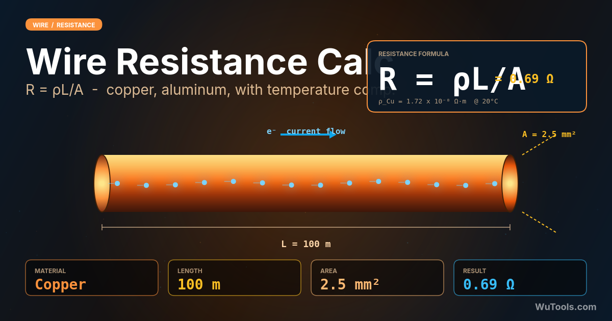
Use R = ρ × L / A, where ρ is the material's resistivity in Ω·m, L is the wire length in meters, and A is the cross-sectional area in m². For round wire, A = π × (d/2)². Example: 100 m of 2.5 mm² copper at 20°C has R = (1.72×10⁻⁸) × 100 / (2.5×10⁻⁶) = 0.688 Ω. The calculator above does all unit conversions automatically and lets you input AWG, mm, or inch diameter with length in meters or feet. For real-world applications include temperature correction (most metals' resistance rises ~0.4% per °C above 20°C) because conductors carrying load run hotter than ambient and resistance grows with temperature.
In metallic conductors, free electrons carry current by drifting through the crystal lattice of metal atoms. At higher temperatures, the atoms vibrate more violently, scattering electrons more frequently and impeding their motion — this raised collision rate manifests as higher electrical resistance. The relationship is approximately linear over normal operating ranges: R(T) = R₀ × [1 + α × (T − T₀)], where α is the temperature coefficient (~0.00393/°C for copper, ~0.00403/°C for aluminum, ~0.0045/°C for tungsten). For semiconductors and carbon, the opposite is true — resistance falls with temperature because heat liberates more charge carriers. This is why incandescent bulbs draw a huge inrush current at switch-on (cold filament = low resistance) before stabilizing as the tungsten heats up.
At 20°C reference: copper α = 0.00393/°C (resistance rises 0.393% per °C); aluminum α = 0.00403/°C; silver α = 0.00380/°C; gold α = 0.00340/°C; tungsten α = 0.00450/°C (highest among common conductors — why incandescent bulbs work); nickel α = 0.00600/°C; iron α = 0.00500/°C; nichrome α = 0.00040/°C (deliberately low — designed for stable heating elements). At 75°C (typical THW insulation limit), copper resistance is 21.6% higher than at 20°C; at 90°C (THHN limit) it's 27.5% higher. NEC Chapter 9 Table 8 lists DC resistance at 75°C specifically to spare engineers from doing this correction by hand for standard conductors.
Use the actual conductor operating temperature, not ambient or 20°C, for accurate results. Resistance at full load can be 15-25% higher than tabulated 20°C values, which directly translates to higher voltage drop and power dissipation. For sizing decisions and code compliance, NEC tables already assume 75°C or 90°C operation depending on insulation. For thermal modeling, follow this rule: estimate conductor temperature = ambient + (load_fraction)² × (insulation_rating − ambient). Example: AWG 10 THHN at 50% load in 30°C ambient runs near 30 + 0.25 × 60 = 45°C. For precision measurement, RTD-style temperature compensation in the calculator above lets you specify exact operating temperature for any of six common metals.
Power dissipated as heat in a conductor is P = I² × R, where I is current and R is the wire's resistance. This is the fundamental cause of conductor warming and why wires need to be sized for ampacity, not just current capability. Example: 30 A through 100 m of 2.5 mm² copper (R = 0.688 Ω) dissipates 30² × 0.688 = 619 W as heat — equivalent to a small space heater inside the conduit. This is wasted energy paid for at the utility meter, and it raises the conductor temperature. The thermal limit determines safe ampacity; once exceeded, insulation degrades and eventually fails. Resistive losses scale with current squared, so doubling current quadruples losses — a major reason high-current circuits use larger conductors and lower voltages are inefficient for long distance.
For a given power P = V × I, raising voltage lets you reduce current proportionally. Resistive losses are I²R, so halving the current cuts losses by a factor of four. This is why utilities transmit at 138 kV, 345 kV, or 765 kV instead of distribution voltages — for the same power and conductor, the loss percentage at 345 kV is 100× lower than at 34.5 kV. The penalty is needing much heavier insulation and clearances, plus expensive transformers at both ends. For DIY context: that's why electric vehicles use 400-800 V battery packs (lower losses, smaller wires) and why USB-C Power Delivery goes up to 48 V instead of 5 V (more power through the same cable). The wire resistance is the same — voltage just changes how much current must flow through it.
Use the same nominal cross-section but apply two small corrections. First, stranded conductors typically have 2-3% higher DC resistance than solid because the helical lay of strands means each strand is slightly longer than the cable length. Second, manufacturing standards (ASTM B8 for Class B stranding) specify a minimum cross-sectional area, but actual values may be slightly less than the equivalent solid. NEC Chapter 9 Table 8 gives separate columns for solid and stranded resistance and you should use the appropriate one. For AC and especially high-frequency, skin effect makes stranded conductors slightly more efficient than solid because current concentrates on strand surfaces — at 60 Hz the difference is negligible (< 1%) for sizes up through 4/0, but significant above 500 kcmil where skin effect derating begins.
DC resistance depends only on material, length, area, and temperature. AC resistance is higher due to two effects: skin effect (alternating current concentrates near the conductor surface, reducing effective cross-section) and proximity effect (adjacent conductors carrying current alter each other's current distribution). For small conductors at 60 Hz, the difference is negligible — AWG 4/0 copper has DC resistance 0.0608 Ω/1000ft and AC resistance ~0.062 Ω/1000ft. But for 1000 kcmil at 60 Hz, AC resistance is about 10% higher than DC. At RF frequencies (kHz to MHz), skin effect dominates and effective resistance can be 10-100× DC values — which is why high-frequency RF inductors use Litz wire (many thin insulated strands woven together) to maximize conductive surface and minimize skin effect losses.
The NEC does not mandate a hard voltage-drop limit, but FPN/Informational Notes in 210.19(A) and 215.2(A) recommend a maximum 3% drop on a branch circuit and 5% total (feeder + branch combined). To check: enter your conductor (material, size, length), then in the Voltage Drop panel add the Load current (A) and System voltage (V), pick single-phase or three-phase, and one-way or round-trip. The calculator computes Vdrop = (2 for single-phase round-trip, or √3 for three-phase) × I × R, the percent drop, and the I²R power loss, then shows a green PASS (≤3%), yellow Caution (3-5%), or red FAIL (>5%) badge against the NEC recommendation. If you FAIL, increase wire size (lower AWG / larger mm²) or shorten the run until the percentage drops below 3%.
Size first for ampacity (NEC 310.16) so the conductor can safely carry the load current, then verify voltage drop on the long run — for distant loads the voltage-drop check usually forces a larger size than ampacity alone. Workflow: set the target voltage drop (3% of system voltage), then required resistance R = Vdrop_allowed / (factor × I), where factor = 2 for single-phase round-trip or √3 for three-phase. Convert R back to a conductor: A = ρ × L / R. Example: 30 A at 240 V single-phase over 100 m one-way (200 m round-trip) allows 7.2 V drop, so R ≤ 7.2 / (2 × 30) = 0.12 Ω, needing roughly 14 mm² (about AWG 6) copper instead of the 2.5 mm² that ampacity alone might suggest. Enter candidate sizes above and read the PASS/FAIL badge to confirm before specifying the conductor.