What is a Voltage Drop Calculator?
A voltage drop calculator is a specialized electrical engineering tool that calculates the voltage loss in electrical circuits due to wire resistance. This essential tool helps electrical engineers, electricians, and technicians determine the proper wire size and ensure adequate voltage at the load end.
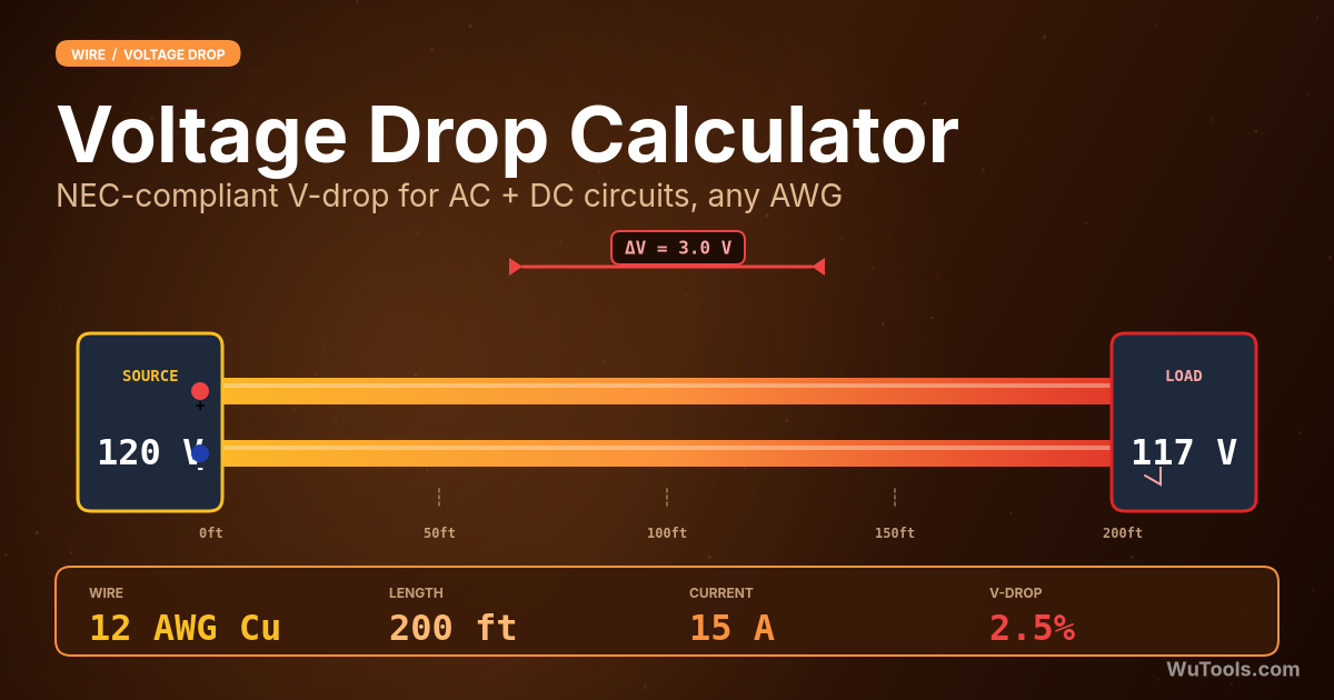
Voltage drop occurs when current flows through a conductor (wire) due to the inherent resistance of the material. The longer the wire or the smaller its cross-sectional area, the greater the voltage drop. This calculator helps optimize wire selection for electrical installations.
How the Voltage Drop Calculator Works
Our calculator uses Ohm's law and wire resistance formulas to determine voltage drop:
1. Calculate wire resistance: R = ρ × L / A (where ρ = resistivity, L = length, A = cross-sectional area)
2. Calculate voltage drop from the one-way resistance: V_drop = 2 × I × R_one-way (for DC and AC single phase, accounting for the out-and-back path) or V_drop = √3 × I × R_one-way (for AC three phase, balanced line-to-line)
3. Calculate percentage: % = (V_drop / V_supply) × 100
Voltage Drop Formulas
The voltage drop calculation depends on the current type:
Basic Formulas
Wire Resistance:
R =
ρ × LA
Where: ρ = resistivity (Ω·m), L = length (m), A = cross-sectional area (m²)
Voltage Drop by Current Type
DC / AC Single Phase: Vdrop = 2 × I × Rone-way
AC Three Phase: Vdrop = √3 × I × Rone-way
Rone-way = ρ × L / A uses the one-way conductor length. The factor 2 accounts for the out-and-back current path; √3 reflects the line-to-line relationship in balanced three-phase systems.
Percentage Voltage Drop
% Drop =
VdropVsupply
× 100
- DC circuits: V_drop = 2 × I × R_one-way
- AC Single phase: V_drop = 2 × I × R_one-way
- AC Three phase: V_drop = √3 × I × R_one-way
- One-way wire resistance: R_one-way = ρ × L / A
- Cross-sectional area: A = π × (d/2)²
Key Features of Our Voltage Drop Calculator
- Support for multiple wire materials (copper, aluminum, silver, etc.)
- DC and AC circuit calculations (single and three phase)
- Multiple wire size units (AWG, inches, millimeters)
- Length units in feet and meters
- Real-time calculation updates
- Professional-grade accuracy
- Mobile-friendly responsive design
- Free to use with no registration
- Custom resistivity input
- Percentage voltage drop calculation
Professional Applications
- Electrical system design and planning
- Wire sizing for electrical installations
- Power distribution system analysis
- Renewable energy system design
- Industrial electrical installations
- Residential and commercial wiring
- Automotive electrical systems
- Telecommunications infrastructure
- Electrical code compliance
- Troubleshooting voltage issues
Voltage Drop Standards
Understanding voltage drop limits and standards:
- NEC (National Electrical Code): 3% for branch circuits, 5% total
- IEC 60364: 4% for lighting circuits, 5% for other circuits
- BS 7671 (UK): 4% for lighting, 5% for other circuits
- AS/NZS 3000 (Australia): 5% maximum voltage drop
- Local electrical codes may vary
- Consider future load growth
- Account for temperature effects
- Include safety margins
Calculation Examples
Example 1: DC Circuit
Given: AWG 12 copper wire, 50 feet one-way (15.24 m), 10A current, 120V supply
One-way resistance:
Rone-way =
1.72×10⁻⁸ × 15.243.31×10⁻⁶
= 0.0792 Ω
Voltage drop: Vdrop = 2 × 10 × 0.0792 = 1.584V
Percentage drop: % =
1.584120
× 100 = 1.32%
Example 2: AC Single Phase
Given: AWG 14 copper wire, 100 feet one-way (30.48 m), 15A current, 240V supply
One-way resistance:
Rone-way =
1.72×10⁻⁸ × 30.482.08×10⁻⁶
= 0.252 Ω
Voltage drop: Vdrop = 2 × 15 × 0.252 = 7.56V
Percentage drop: % =
7.56240
× 100 = 3.15%
Tips for Using the Voltage Drop Calculator
- Always use one-way length for calculations
- Consider the highest expected current
- Account for temperature derating factors
- Use the correct wire material resistivity
- Check local electrical codes for limits
- Consider future expansion and load growth
- Round up to the next larger wire size if needed
- Verify calculations with multiple methods
- Consider voltage drop at peak loads
- Include all circuit components in calculations
Frequently Asked Questions
Voltage drop is calculated by multiplying current by wire resistance: V_drop = I × R. The wire resistance itself depends on three factors — material resistivity, length, and cross-sectional area, combined as R = ρ × L / A. For DC circuits the result is direct; for AC single-phase you multiply by 2 (round-trip current) and for three-phase by √3. The free online calculator on this page handles all three current types and lets you input wire size in AWG, inches, or millimeters. Always use the one-way length of the wire run — the formula already accounts for the return path internally. The percentage drop, computed as (V_drop / V_supply) × 100, is what most electrical codes regulate.
The 3% rule comes from the US National Electrical Code (NEC) recommendation in Article 210.19 (Informational Note 4) and 215.2: branch circuits should not exceed 3% voltage drop, and the combined branch + feeder drop should not exceed 5%. While these are recommendations rather than hard requirements in the NEC, most jurisdictions enforce them, and they exist because excessive voltage drop causes motors to overheat, LED drivers to flicker, electronics to reset, and resistive loads to underperform. IEC 60364 in Europe uses 4% for lighting and 5% for other circuits. If your calculated drop exceeds these limits, upsize the conductor by one or two AWG sizes or shorten the run.
After you calculate, pick a standard from the Compliance standard menu — NEC 3% branch, NEC 5% total, IEC 4% lighting, IEC 5% other, or a custom percentage. The tool compares your computed percentage drop against that limit and shows a green PASS or red FAIL badge with the exact numbers. When a run fails, it does the sizing work for you: it loops through standard AWG sizes (14, 12, 10, 8, 6, 4, 3, 2, 1, 1/0, 2/0, 3/0) using the same resistance math, your material, length, current, voltage and phase, and recommends the smallest conductor that brings the drop within the limit. That turns the calculator from a raw voltage readout into a conductor-selection aid for long runs, EV chargers, solar PV and well pumps — no more eyeballing the result against a remembered code limit.
Copper has about 61% lower resistivity than aluminum (1.72×10⁻⁸ vs 2.82×10⁻⁸ Ω·m), so for the same wire size copper produces significantly less voltage drop. However, aluminum is roughly one-third the weight and one-third the cost of copper, which matters for long service entrances and utility feeders. The trade-off: aluminum requires you to go up about two AWG sizes to match copper's ampacity and resistance — so a 4 AWG copper feeder typically becomes 2 AWG aluminum. For runs over 100 feet at higher currents, aluminum often wins on total installed cost despite the larger conductor. Always use connectors and terminations rated for aluminum (marked AL/CU) to prevent corrosion-related failures.
This calculator computes the one-way conductor resistance R_one-way = ρ × L / A, then applies an explicit per-phase multiplier so the math matches the worked examples on this page. For DC and AC single-phase, V_drop = 2 × I × R_one-way — the factor 2 accounts for the current flowing out along one conductor and back along the return (neutral) conductor. For balanced AC three-phase, V_drop = √3 × I × R_one-way, which comes from the line-to-line voltage relationship (the three phase currents share the return so there is no doubling, but the line-to-line drop is √3 times the per-phase drop). These are the resistive-only formulas; for motors and inductive loads on long runs, a fuller model adds reactance: V_drop = k × I × (R·cosφ + X·sinφ) × L, where φ is the power factor angle and X is reactance.
Copper resistivity increases by about 0.393% per °C and aluminum by 0.403% per °C above the 20°C reference. So a copper conductor operating at 75°C — the typical limit for THW insulation — has about 21.6% higher resistance than its 20°C tabulated value. This means real-world voltage drop in a fully-loaded circuit is materially worse than nominal calculations suggest. For accurate sizing, either use the resistivity at the actual operating temperature, or apply a derating factor: multiply the nominal voltage drop by 1.05 to 1.20 depending on insulation rating and ambient conditions. The NEC Chapter 9 Table 8 lists DC resistance at 75°C specifically to account for this.
Always enter the one-way length — the distance from source to load along a single conductor. The calculator's formula multiplies by 2 internally for DC and single-phase AC to account for the return path through the neutral or return conductor. For three-phase systems with a balanced load and no neutral current, you use the one-way length without doubling because the three phase currents sum to zero at the neutral point. Confusion about this is one of the most common errors in electrical estimating: entering 200 ft for a 100 ft run will double your calculated drop and lead to oversized conductors and wasted material. When in doubt, measure the actual conduit run plus a 10% allowance for bends and slack.
Real-world AC loads draw current that is not perfectly in phase with voltage. The power factor (cosφ) reduces the effective resistive drop component but adds a reactive drop. The full three-phase formula is V_drop = √3 × I × L × (R·cosφ + X·sinφ), where R and X are per-meter or per-foot values from cable manufacturer tables. For motors with PF = 0.8 lagging, the reactive term can add 10-30% to the drop calculated from R alone, especially in larger conductors where reactance dominates over resistance. For conductor sizes 1/0 AWG and above, always include reactance from NEC Chapter 9 Table 9 (impedance for AC conductors in conduit) rather than relying solely on DC resistance.
Ampacity tables tell you the minimum size to prevent insulation damage from heat, but voltage drop is a separate constraint that often dictates a larger conductor on long runs. A common scenario: a 20-amp circuit run 150 feet on 12 AWG copper produces about 6% drop at full load — well past the 3% recommendation, even though 12 AWG is rated for 20 amps. Upsizing to 10 AWG cuts the drop to ~3.7%, and 8 AWG to ~2.3%. The rule of thumb: for every 100 feet beyond 100 feet of run length, increase conductor size by one AWG step. For solar PV, EV chargers, and well pumps where continuous loads run for hours, undersized conductors cost real money in lost energy every day.